|
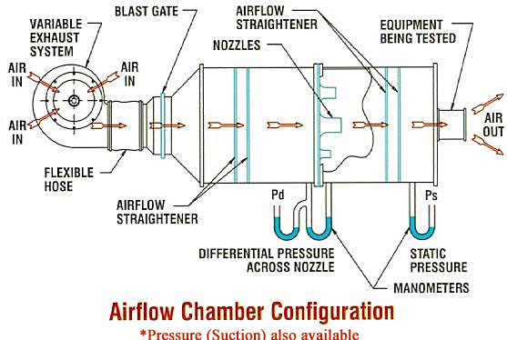
The chambers are designed in accordance with AMCA 210-99/ASHRAE 51-1999 and have been sized for convenient flow ranges. The chamber diameter is determined by the size of the axial flow fan to be tested and the maximum flow range desired. The minimum flow range is determined by the nozzle array and the standard is 3CFM. Lower flow ranges may be achieved by utilizing smaller nozzles in the nozzle array.
|
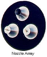 |
The nozzles are sized so that there is adequate overlap for different nozzles and they are positioned on the plate so that they may be used in parallel to achieve higher flow ranges. Stoppers are provided to block off nozzles not in use and are easily removed for different ranges of testing. |
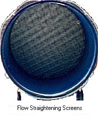
| The chamber has flow straightening screens installed upstream and downstream of the nozzle array. The screens break up turbulence in the airstream and provide a uniform flow approaching the nozzle array. Each set consists of three screens with open areas of 60%, 50% and 45%. |
|
|
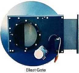
The flow through the chamber is controlled with a sliding gate valve called a blast gate. By opening the blast gate, the flow is varied through the chamber to provide test data from shut off (no flow) to free delivery (no back pressure) for fan performance evaluation.
|
|
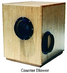
The counter blower is used to help overcome the resistance of the nozzle array, blast gate and ducting so that free delivery may be achieved for fan performance evaluation. It is also used as an air source for system inpedance measurements and thermal resistance data.
|
|
|
The speed is varied with a solid state speed controller so that adjustments in voulume flow may be optimized by coordinating the blast gate and the speed of the counter blower. Lower counter blower speeds also result in less acoustic noise in the laboratory. The blowers are enclosed for safety and noise attenuation.
|