INSTRUCTION MANUAL
FOR
AMCA 210-99
AIRFLOW TEST
CHAMBER
AIRFLOW MEASUREMENT SYSTEMS
P.O. BOX 2491
CHULA VISTA,
CA 91912
TEL: (619)
426-4202
e-mail: fantester@yahoo.com
INTRODUCTION
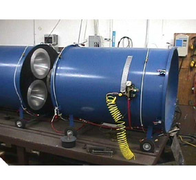
The airflow test chamber is designed in accordance with AMCA 210-99 and may be used for measuring fan performance and/or system impedance. The chamber is designed with multiple nozzles to cover the full airflow range of the design. The chamber crossectional area should be approximately 16 times the crossectional area of the axial fan under test.
The chamber is constructed with pressure taps on
each side of the nozzle to measure the differential pressure. The pressure taps
near the end of the chamber is for measuring the static pressure of the fan
under test or the pressure drop across the system under test. In either case, the measurement is a
differential pressure between the chamber and atmospheric pressure.
The nozzle selection is based on a differential pressure
between 0.1 inches w.g. and 4.0 inches w.g. The lower limit (0.1 inches w.g.)
is used to ensure the flow in the nozzle is fully turbulent and the higher
limit (4.0 inches w.g.) is used so compressibility is not a factor (4.0 inches
w.g. is approximately 1% of an atmosphere).
SET UP CONFIGURATION
The chamber is shipped with the nozzle plate stored in place of the front plate. The nozzle plate should be removed and stored in a secure place and the front plate inserted. The nozzle plate is plate between the two sections and the blast gate is on the exit of the chamber. The flex duct goes between the flange on the blast gate and the counter blower.
PRESSURE SET UP
To reverse the airflow and set up the suction mode, simply remove the nozzle plate and rotate the plate 180 degrees. Reconnect the blast gate assembly and connect the flex duct to the outlet of the counter blower.
SUCTION SET UP
The
primary difference between pressure and suction is with pressure, airflow is
INTO the chamber and with suction airflow is OUT OF the chamber. In the
pressure mode, the flex duct is connected between the inlet of the counter
blower and the blast gate and in the suction mode it is connected between the
outlet of the counter blower and the blast gate. The nozzles ALWAYS face
downstream (in the direction of airflow).
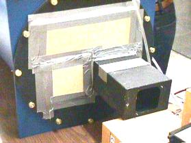
BLAST GATE
The blast gate is at the end of the chamber and is a sliding gate valve. The blast gate is used in conjunction with the speed controller/counter blower to vary the flow through the chamber.
BLAST GATE
INFLATABLE SEALS
The seals on each side of the nozzle plate and at
the front plate are inflated by using shop air or the compressor supplied with
the system. The air hose is connected to the regulator and the regulator should
be set for a MAXIMUM PRESSURE OF 15
PSIG. Once the seals are inflated, the chamber is sealed. In some
cases, there may be minimal leakage from the seals and care should be taken to
ensure there is adequate pressure.
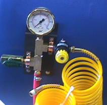
PRESSURE MANIFOLD
To deflate the seals, turn the valve on the right.
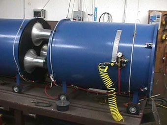
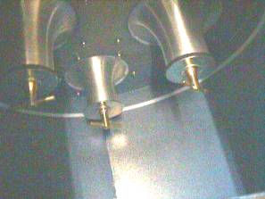
NOZZLE
ARRAY
The nozzle array is in the center of the chamber and
is accessed by deflating the seals and separating the two sections.
NOZZLE PLATE
The flow range to be covered is determined by the nozzle diameter. In order to have better resolution, the maximum flow should be near the 3.0+ inches w.g. range in differential pressure. If the flow range is unknown, select the 2.0 inch diameter and check free delivery to verify nozzle selection. If the differential pressure is below 1 inch w.g., select a smaller nozzle. If the differential pressure exceeds 4.0 inches w.g., select a larger nozzle or combination of nozzles.
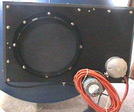
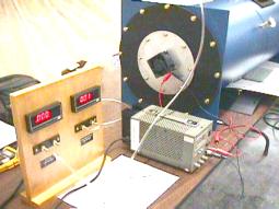
COUNTER BLOWER
The counter blower is wired to the speed controller. Verify that rotation of the counter blower
is counter clockwise when viewing the inlet. If the rotation is not
correct, switch any two of the leads from the counter blower to the speed
controller.
MANOMETER CONNECTIONS
There are two types of manometer panels. One has 4 inclined manometers and the other has two digital manometers. In either case, the left-hand port is for positive pressure and the right hand port is for negative pressure.
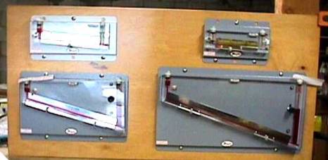
INCLINED MANOMETER PANEL
The manometer should be leveled (inclined) and zeroed prior to testing. The 0-6 inch inclined manometer is recommended for measuring the differential pressure. The two pressure taps in the center of the chamber are on either side of the nozzle plate. The one on the left (in pressure set up) is the high pressure and is connected to the left-hand side of the manometer. The tap downstream is the low pressure tap and is connected to the right hand side of the manometer.
FAN PERFORMANCE TESTING
The purpose of this test is to determine the aerodynamic characteristics of the fan under test. The data will be taken from no flow (shut off) to free flow (free delivery) and the data points will be used to plot the performance curve.
TYPICAL AXIAL FLOW PERFORMANCE CURVE
The number of data points may vary from fan to fan. However, enough points should be taken to fully define the curve. Excessive points are not harmful, just time consuming.
SET UP
The set up for the test is the most critical and time consuming part of the test. The nozzle selection is based on the flow range desired. Check the calibration curves for the minimum and maximum flow for the nozzle to verify it covers the range desired. Changing nozzles during the test is acceptable to extend the range. The nozzles ALWAYS point downstream. The access door is downstream of the nozzle plate.
The differential pressure is measured with the two hose barbs in the center of the chamber. The static pressure is measured with the hose barb closest to the front plate and the pressure will be positive for airflow into the chamber.
The fan to be tested is mounted on the front plate of the chamber. Care should be taken to ensure the fan is sealed adequately to prevent leakage.
The picture below shows a typical axial flow fan mounted on the front of the chamber and the connections to the digital manometer panel.
TYPICAL PRESSURE SET UP FOR AXIAL FLOW FAN
Once the set up is complete, the test is ready to begin. The first data point is at the no flow or shut off condition. Since there may be some leakage around the blast gate, if an absolute shut off point is desired, insert all the stoppers in the nozzles and take the first data point. Typical data recorded will be static pressure, differential pressure (0 in this case), speed, power and/or current. Since the volume flow (CFM- cubic feet per minute) is directly proportional to speed and the static pressure is a function of speed squared, the speed of the fan is essential if comparing one fan to another aerodynamically.
Once the shut off point is recorded, remove the stopper from the nozzle that has been selected. Start the counter blower on a low speed (approximately 15 Hz.) and slowly open the blast gate until 0.1 inches w.g. is measured for the differential pressure. Allow the fan to stabilize and record the data.
Proceed by opening the blast gate and take data points to determine the performance curve. The static pressure will decrease and the differential pressure increases. The CFM is a square root function of the differential pressure so the increments between differential pressure readings should be increased as you proceed along the curve (e.g. 0.1, 0.2, 0.4, 0.7, 1.0, 1.5,etc). When the blast gate if completely opened, increase the speed on the counter blower until free delivery is reached (0 static pressure).
The fan test is now complete. Shut off the counter blower and plot the data to verify the data points fully define the fan performance curve. The Excel spreadsheet may be used to calculate and plot the data.
SYSTEM IMPEDANCE TESTING
The purpose of the system resistance test is to determine the pressure required to move the appropriate amount of volume flow through the system. The chamber configuration is determined by the inlet and outlet situation of the unit to be tested. If the outlet is easily accessible, the airflow may be drawn through the unit being tested and the pressure set up is used. If the inlet is more accessible, the chamber should be reversed and the suction set up may be used.
For the impedance test, the air is forced through the unit to be tested and the pressure drops are measured for various flow points.
TYPICAL SYSTEM RESISTANCE CURVE
Install the unit to be tested on the front of the chamber and seal to prevent leakage.
UNIT TO BE TESTED
ON FRONT OF CHAMBER
Open the blast gate all the way and secure with the thumb
screw. Start the counter blower and draw (or blow) air through the unit to be
tested. The first data point should be a minimum of 0.1 inches w.g.
differential pressure. If the static pressure (pressure drop across the unit to
be tested) is not readible, increase the flow unit it is.
Continue taking data points by increasing the speed of the
counter blower. Both the static pressure and the differential pressure will
increase. Normally five or six data points are sufficient.
If the data points are plotted on log-log paper, they will
be in a straight line with a slope of approximately 2. The equation for system
resistance is as follows:
DP=k(CFM)n
where 1 £ n £ 2 and k is a constant of the system
When n=1, the flow is fully laminar and when n=2, the
flow if fully turbulent. In most cases, n » 1.8. If the slope of the data curve is less than
1 or greater than 2, there was probably leakage and the data should be
verified.
DETERMINING FLOW THROUGH THE SYSTEM
Once the fan performance curve and the system
impedance curve has been established, by overplotting the two curves, the
intersection of the two curves is the theoretical operating point of the fan in
the system.
INTERSECTION
OF FAN AND IMPEDANCE CURVE
The reason that this is a theoretical operating point is
that the fan performacne curve was run without any obstructions upstream or
downstream of the fan. By placing the fan in the system, the fan performance
may be effected.
To determine the actual operating point of the fan in the
system. With the unit to be tested still attached to the chamber, energize the
fan. The chamber will act as an
impedance to the fan so there will be a positive (or negative depending on flow
direction) static pressure. Using the
counter blower, increase the speed until the static pressure is zero. This
represents free delivery operation as if the unit was setting on a table.
Measure the differential pressure at that point and the flow is what you will
get during actual operation.
If the flow is significantly less than the point of the
intersection of the curves, the fan may be adversely effected by conditions upstream or downstream of the
fan. The general rule of thumb is to have one-half diameter of the fan clear
upstream and downstream of the fan.
CORRECTIONS FOR DENSITY
The pressures (differential and static) will vary with the
density of the air. If the air is significantly different from standard air
(29.92 In. Hg, 70°F)
corrections may be necessary.
Using the perfect gas law, we can ratio the DPc which
is the corrected pressure to the actual pressure DPa.
DPc = DPa x Ta x 29.92
529.6 x
Pa
where DP
is the static or differential pressure to be corrected, Ta is the actual absolute (°R) temperature, and Pa is the barometric pressure in inches
Hg.
Basically, for every 4.5°F
variation in temperature there is a 1% change in density and the corresponding
pressure.