|
The amount of air required to cool a system may be calculated quite accurately when the power dissapated and temperature rise is known. The pressure required to force the air through the system is not easy to calculate and should be measured in order to select the optimum airmover for the application. If an improper selection is made the power input to airmover, size, and acoustic noise may be considerably higher. If the estimate is too low, inadequate heat transfer will result in overheating.
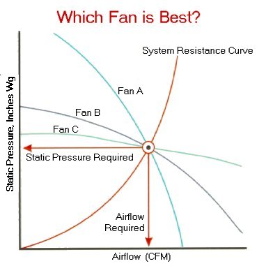
The Airflow test chambers may be used to determine the aerodynamic performance of a fan or blower. The airmover is mounted on the front of the chanber and the static pressure versus volume flow is measured. The performance of different fans may be compared to select the optimum airmover for a given application. The Airflow test chambers are used to measure the pressure required to force a given volume of air through the system. By using the test chamber, a system resistance curve may be generated to help select the airmover. The theoretical operating point is the intersection of the system resistance curve and the fan curve. The inlet and outlet conditions affect the fan performance and the chamber may be used to accurately measure the actual volume of air that is going through the system. In addition, the chamber may be used to determine thermal resistance. The chamber may be used as the airsource for the system. By energizing the system, a given volume of air may be drawn through the system and the temperature rise measured. By determining several points, the plot of temperature rise versus mass flow shows thermal resistance. If a system is to be deployed in nonstandard conditions (altitude), the thermal resistance plot will determine the new temperature rise at that altitude and the ambient temperature limits may have to be adjusted. |